Appearance
BPMN Workflow Tutorial for PLANQK Platform
Welcome to the complete guide for creating and managing BPMN workflows on the PLANQK platform! This tutorial will take you from the basics to building complex quantum workflows that orchestrate multiple services.
What You'll Learn
By the end of this tutorial, you'll be able to:
- Understand BPMN fundamentals and workflow concepts
- Create your first quantum workflow service on PLANQK
- Use the visual workflow modeler effectively
- Design both sequential and parallel service execution
- Implement proper data flow between services
- Create reusable workflow APIs
- Follow best practices for production workflows
Why Use Workflows?
Workflows solve a key challenge in quantum computing: **orchestrating complex, multi-step processes ** without manual programming. Instead of writing Python code to integrate individual PLANQK services, you can:
✅ Visually design your process flow using BPMN diagrams
✅ Automate service execution with built-in error handling
✅ Handle long-running processes (hours to weeks) reliably
✅ Monitor progress in real-time
✅ Reuse workflows as standalone PLANQK services
✅ Bridge technical and business requirements for better collaboration
Prerequisites
Before starting this tutorial:
- Be familiar with basic quantum computing concepts
- Have subscriptions to the PLANQK services you want to orchestrate
If you want to follow the examples in this tutorial, you can subscribe to the following services:
To subscribe to these services, create a new application on the PLANQK platform > applications. You can create subscriptions to the services by selecting your new application when clicking the Subscribe button on the details page of the respective service in the marketplace.
Part 1: Understanding BPMN Basics
Before diving into workflow creation, let's understand the fundamentals of BPMN (Business Process Model and Notation).
What is BPMN?
BPMN is a standardized visual language for modeling business processes. On PLANQK, we use BPMN 2.0 to define how quantum services should be executed and how data flows between them.
Key BPMN Elements for PLANQK Workflows
| Element | Symbol | Icon | Purpose |
|---|---|---|---|
| Start Event | ○ |  | Marks where your workflow begins |
| End Event | ● |  | Marks where your workflow ends |
| PLANQK Service Task | ▢ |  | Executes a subscribed PLANQK service |
| Parallel Gateway | ◇+ |  | Splits flow to run tasks in parallel |
| Sequence Flow | → | → | Shows the order of execution |
Example: Simple Sequential Workflow
○ → [Generate Circuit] → [Execute on Backend] → [Send Results] → ●Example: Parallel Execution Workflow
○ → [Generate Circuit] → ◇+ → [Backend 1] → ◇ → [Send Results] → ●
                          └ → [Backend 2] → ┘
Part 2: Creating Your First Workflow Service
Step 1: Create the Service
Navigate to the PLANQK service creation page
Select "Create New Service" and choose "Quantum Workflow Service".
Fill in the required information:
Property Description Example Name Choose a meaningful name for your service "Quantum Benchmarking Workflow" Service Type Select "Quantum Workflow Service" Quantum Workflow Service Summary Brief description for the marketplace "Automated benchmarking across multiple quantum backends" Description Detailed explanation of what your workflow does "This workflow generates benchmark circuits, executes them on multiple quantum computing backends in parallel, and sends results via email notification." Click "Create Service" to proceed
Step 2: Access the Workflow Modeler
- Click on your newly created workflow service
- Navigate to the "Workflow" tab
- You'll see the visual workflow modeler with a single Start Event (○)
Part 3: Building Your First Workflow - Practical Example
Let's build a real quantum benchmarking workflow step by step. This workflow will:
- Generate a benchmarking circuit
- Execute it on multiple quantum backends in parallel
- Send results via email when complete
Understanding the Workflow Modeler Interface
In the following image, you can see the main components of the workflow modeler:
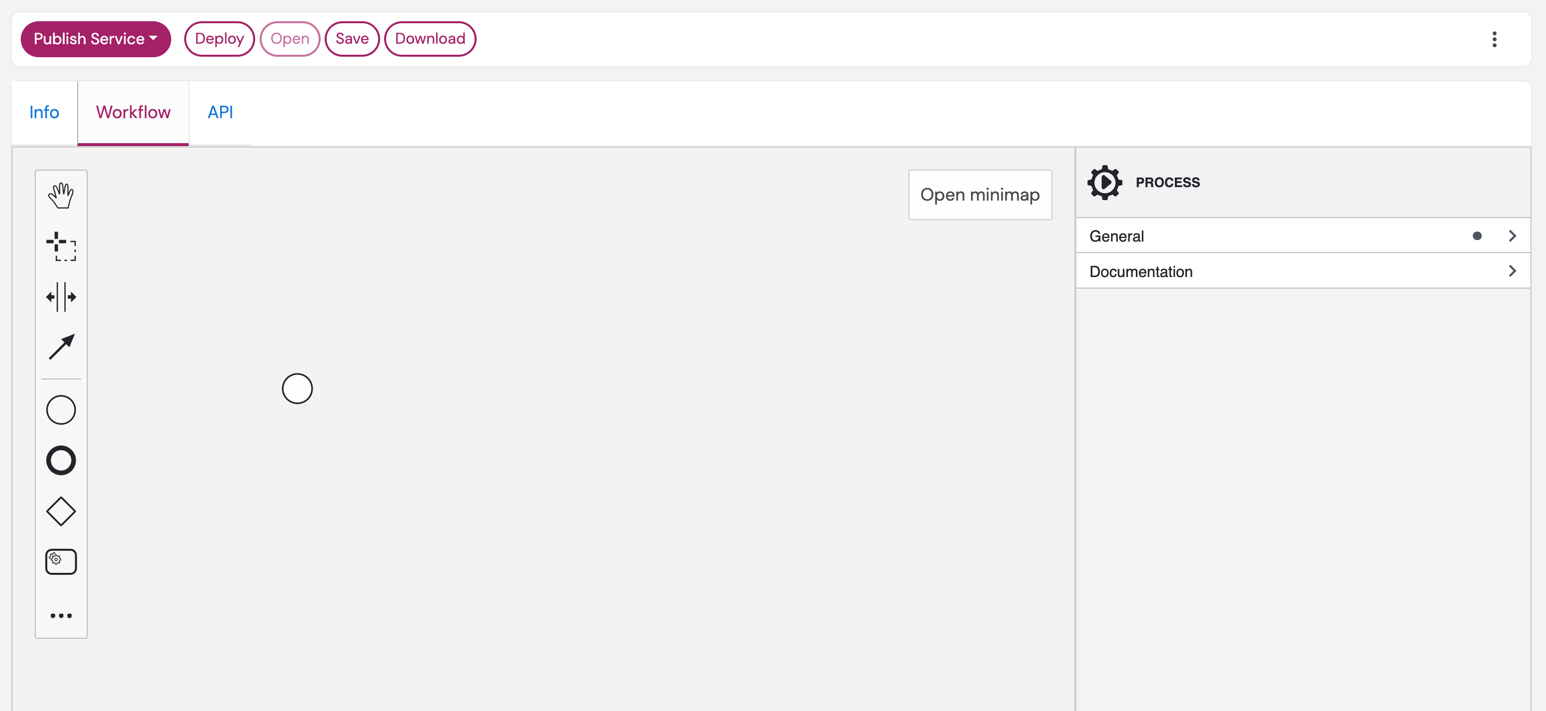
The Canvas
- Central workspace where you design your workflow
- Initially shows only a Start Event (○)
- Drag and drop elements from the palette to build your workflow
The Palette (Left Side)
- Contains all BPMN elements you can use
- Common elements are visible by default
- Click "..." for advanced elements (loops, conditional flows, etc.)
Essential Elements for PLANQK
- PLANQK Service Task (▢): Calls a subscribed PLANQK service
- Parallel Gateway (◇+): Creates parallel execution paths
- End Event (●): Marks workflow completion
- Sequence Flow (→): Connects elements to show execution order
The Properties Panel (Right Side)
- Displays configuration options for the selected element
- Use it to set properties like service names, input/output variables, and more
- Click on any element to see its properties here
Step-by-Step: Building the Control Flow
Step 1: Add Your First Service Task
- From the palette, drag a PLANQK Service Task (▢) onto the canvas
- Position it to the right of the Start Event
- Connect the Start Event to the task:
- Click on the Start Event (○)
- Drag the appearing arrow to the PLANQK Service Task
Step 2: Configure the Service Task
- Click the wrench icon (🔧) on the task
- In the configuration panel, select the
MQT Benchmarkingservice from the dropdown. This service will generate a quantum circuit for benchmarking. - In the properties panel on the right, select the General tab.
- Give the task a descriptive name, e.g., "Generate Benchmark Circuit", instead of the default name for more clarity.
Step 3: Add Parallel Execution
For running the circuit on multiple backends simultaneously:
Add a Parallel Gateway:
- Drag Parallel Gateway (◇+) from the palette
- Place it after your benchmarking task
- Connect the benchmarking task → parallel gateway
Add Backend Execution Tasks:
- Drag two PLANQK Service Tasks for different backends
- Position them below the parallel gateway
- Connect the parallel gateway to each task:
- Click the parallel gateway
- Drag arrows to each task
- Configure each task to use a different backend service by clicking the wrench icon (🔧) and selecting the appropriate service:
- For the first task, select
IonQ Simulator Execution Service - For the second task, select
mqt-ddsimand give it a name like "MQT Simulator"
- For the first task, select
Add Synchronization Gateway:
- Drag another Parallel Gateway after the backend tasks
- Connect both backend tasks to this synchronization gateway
- This ensures both backends complete before continuing
Step 4: Add Final Steps
Add Email Notification:
- Drag a PLANQK Service Task after the synchronization gateway
- Configure it to use an email notification service
- Name it "Send Results Email"
Add End Event:
- Drag an End Event (●) from the palette
- Connect the email task to the end event
Save Your Workflow:
- Click the Save button in the top left
Your Complete Workflow Should Look Like:
○ → [Generate Circuit] → ◇+ → [IonQ Simulator] → ◇+ → [Send Email] → ●
                          └ -→ [MQT Execution] → ┘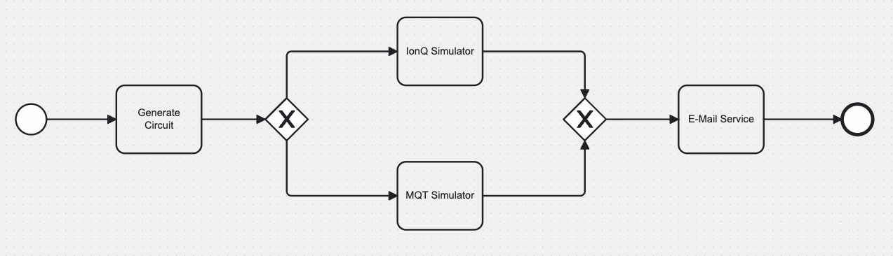
Step-by-Step: Implementing Data Flow
Data flow defines how information (like quantum circuits, results, parameters) moves between services in your workflow.
Understanding Data Variables
Each service in your workflow can:
- Receive input data from previous steps
- Produce output data for following steps
- Access workflow parameters (like email addresses, benchmark names)
Step 1: Define Workflow Input Parameters
When you want your workflow to receive input from external sources (API calls), you must configure the **Start Event ** with a manual request example that defines the expected input structure. The corresponding OpenAPI specification will be generated automatically based on this configuration.
- In the workflow modeler, select the Start Event (○)
- In the properties panel, navigate to the "API Description" section
- Define an example input your workflow will acceptjson
{
  "benchmark_name": "ghz",
  "email_recipient": "your-email@your-company.domain"
}
This manual request example serves multiple purposes:
- Each key in the JSON corresponds to a workflow variable
- Documents the API interface for external systems
- Provides examples for testing and integration
The field names from your manual request example become workflow variables that can be referenced directly in service task configurations. For example, benchmark_name and email_recipient can be used in subsequent service tasks to pass the data as input.
Step 2: Configure Service Task Data Mapping
When you select a service task in your workflow, you need to configure how data flows in and out. Click the service task to open the properties panel on the right.
To provide input and output data for the service task, you can use FEEL expressions.
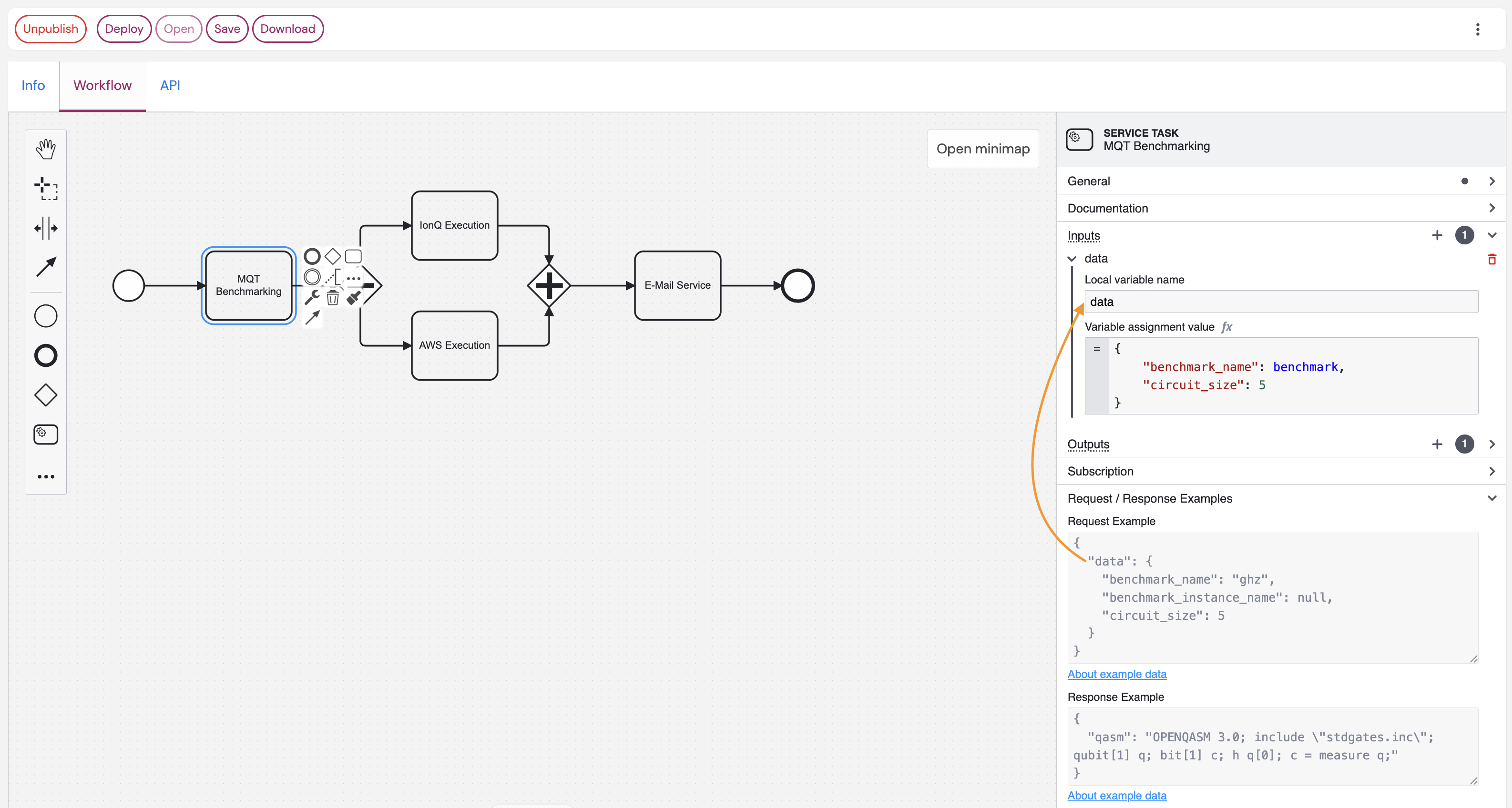
Setting Up Input Variables
- Select the "Generate Benchmark Circuit" service task.
- Navigate to the "Inputs" section in the properties panel.
- Add input variables by clicking the
+button. - Define the "local variable name". This is maps to the service's request elements that it expects as input. Use the exact names as shown in the API documentation of the service interface. You can see the API example values in the Request Example panel. In the example shown in the figure above, the only expected input of the service is
dataas printed in the Request Example panel. Thus, usedataas the local variable name to provide a value for the service. - Set values to the variable using JSON format. The expected structure is shown in the API documentation and Request Example panel. For the MQT Benchmarking service, you could set the value of the
datavariable like this:json{ "benchmark_name": "qhz", "circuit_size": 5 } - Use workflow variables directly (without quotes) when referencing data from previous steps. For example, if you have a variable
benchmark_namefrom any previous step, you can use it like this:jsonThis will automatically set the value from the output variable called{ "benchmark_name": benchmark_name, "circuit_size": 5 }benchmark_namewithin the workflow into the JSON object when the service is invoked.
The key points:
- Local variable name:
data(as shown in the service's interface documentation) - Variable assignment value: Maps your input variables to the service's expected input.
- Use the Request Example: The panel shows a "Request Example" - structure your input mapping to match this format.
- Variable references: Use workflow variable names directly (without quotes) when referencing data from previous steps.
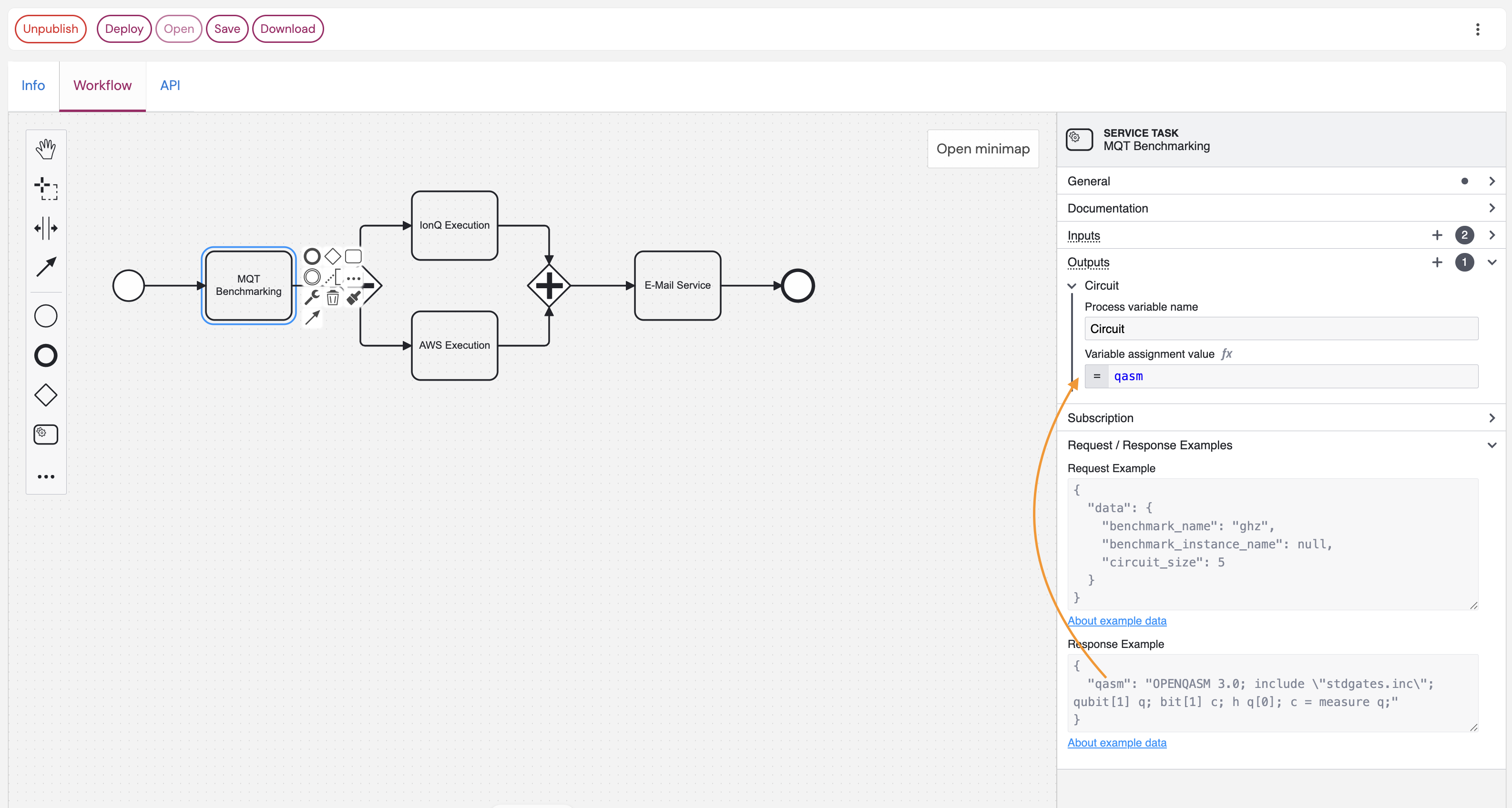
Setting Up Output Variables
- Navigate to the "Outputs" section in the service task configuration.
- Define how to store the service response in workflow variables.
- Use the Response Example: The panel shows a "Response Example" - this tells you what data structure the service will return.
In the example shown below, the generated circuit from the MQT Benchmarking service is returned in the qasm field of the response. It is stored this in a variable called Circuit for use in subsequent tasks.
Practical Data Mapping Examples
MQT Benchmarking Service Configuration Inputs section:
- Local variable name:
data - Variable assignment value:
json
{
  "benchmark_name": benchmark_name,
  "circuit_size": 5
}Outputs section:
- Store the service response (QASM circuit) in variable:
quantum_circuit
IonQ Execution Service Configuration
Inputs section:
- Local variable name:
data - Variable assignment value:
json
{
  "circuit": Circuit
}
Outputs section:
- Store the execution results in variable:
IonqExecutionResultfrom thecountsvalue of the service's response.
MQT Simulator Service Configuration
Inputs section:
- Local variable name:
datawith variable assignment value:json{ "qc": Circuit } - Local variable name:
paramswith variable assignment value:json{ "shots": 100 }
Outputs section:
- Store the execution results in variable:
MqtExecutionResultfrom theresult.countsvalue of the service's response.
Email Service Configuration Inputs section:
- Local variable name:
datawith variable assignment value:json{ "to": email_recipient, "subject": "Benchmark result available", "message": "I'm happy to inform you that the backend execution results are available: IonQ: " + string(IonqExecutionResult) + " MQT DDSIM " + string(MqtExecutionResult) }
Key Tips:
- ✅ Always check the Request/Response Examples in the service task configuration
- ✅ Match the exact JSON structure shown in the Request Example
- ✅ Use workflow variables (like
benchmark,email_recipient) in your mappings - ✅ Store service outputs in descriptive variable names for use by later tasks
- ❌ Don't guess the data format - always refer to the provided examples
Step 3: Advanced Data Flow Patterns
Conditional Data Flow
Use Exclusive Gateways (◇×) to route data based on conditions:
[Check Results] → ◇× → [Success Path] (if results valid)
                   └→ [Error Path] (if results invalid)
Creating a Reusable Service API
Transform your workflow into a reusable service that others can integrate:
Step 1: Define Service Interface
In the "API Description" section of your workflow, create a meaningful example input. Currently, no schema is supported but only the example request.
Step 2: Implement Error Handling
Add Error Boundary Events to handle service failures gracefully:
- Service Timeout: Add timer boundary events to tasks
- Service Errors: Add error boundary events with retry logic
- Notification: Always notify users of both success and failure cases
Part 4: Best Practices & Advanced Patterns
Workflow Design Best Practices
1. Keep It Simple
✅ Do: Start with simple sequential workflows
✅ Do: Add complexity gradually as needed
❌ Avoid: Over-engineering with unnecessary parallel paths
2. Handle Errors Gracefully
✅ Do: Add timeout boundaries to long-running tasks
✅ Do: Implement retry logic for critical services
✅ Do: Always notify users of failures
❌ Avoid: Silent failures or infinite loops
3. Design for Monitoring
✅ Do: Use descriptive task names
✅ Do: Add intermediate checkpoints for long workflows
✅ Do: Log important intermediate results
❌ Avoid: Black-box workflows without visibility
4. Optimize for Performance
✅ Do: Use parallel execution for independent tasks
✅ Do: Minimize data transformations between services
✅ Do: Cache expensive computations when possible
❌ Avoid: Unnecessary sequential bottlenecks
Common Workflow Patterns
Pattern 1: Fan-Out/Fan-In (Parallel Processing)
○ → [Prepare Data] → ◇+ → [Process A] → ◇+ → [Combine Results] → ●
                      └ → [Process B] → ┘
Use when: Processing the same data with multiple services
Pattern 2: Pipeline (Sequential Processing)
○ → [Step 1] → [Step 2] → [Step 3] → [Step 4] → ●Use when: Each step depends on the previous step's output
Pattern 3: Conditional Flow
○ → [Check Condition] → ◇× → [Path A] → ●
                         └→ [Path B] → ●
Use when: Different actions needed based on data or conditions
Pattern 4: Error Handling with Compensation
○ → [Main Task] → [Success Action] → ●
    │
    └→ [Error Handler] → [Cleanup] → ●
Use when: You need to clean up after failures
Troubleshooting Common Issues
Issue: "Service Not Found"
Symptoms: Workflow fails with service subscription error
Solutions:
- Verify you have an active subscription to the service
- Check service name spelling in task configuration
- Ensure service is still available in the marketplace
Issue: "Data Mapping Error"
Symptoms: Service receives wrong data format
Solutions:
- Check input/output variable names match exactly
- Verify data types match service requirements
- Add data transformation script if needed
Issue: "Workflow Timeout"
Symptoms: Workflow stops without completion
Solutions:
- Check individual service timeouts
- Add timer boundary events to long-running tasks
- Implement progress checkpoints
Issue: "Parallel Tasks Don't Synchronize"
Symptoms: Some parallel branches complete but others hang
Solutions:
- Ensure all parallel paths have proper error handling
- Add timeout boundaries to parallel tasks
- Check for data dependency conflicts
Testing Your Workflows
1. Start Simple
- Test individual service tasks first
- Use minimal test data initially
- Verify each step completes successfully
2. Test Error Scenarios
- Simulate service failures
- Test timeout conditions
- Verify error notifications work
3. Performance Testing
- Test with realistic data sizes
- Monitor execution times
- Check resource usage
4. Integration Testing
- Test the complete end-to-end flow
- Verify all data mappings work correctly
- Test with real user scenarios
Production Deployment Checklist
Before publishing your workflow service:
✅ Functionality
- [ ] All service tasks configured correctly
- [ ] Data flow works end-to-end
- [ ] Error handling implemented
- [ ] User notifications working
✅ Documentation
- [ ] Service description clear and accurate
- [ ] API parameters documented
- [ ] Expected outputs defined
- [ ] Usage examples provided
✅ Performance
- [ ] Reasonable execution timeouts set
- [ ] Parallel execution used where beneficial
- [ ] Resource usage optimized
✅ Reliability
- [ ] Error handling tested
- [ ] Retry logic implemented
- [ ] Monitoring and logging configured
Advanced Features
Looping and Iteration
Use Loop Characteristics on tasks to repeat operations:
- Standard Loop: Repeat a fixed number of times
- Multi-Instance: Process array data in parallel
- Sequential Multi-Instance: Process array data one by one
Conditional Logic
Use Exclusive Gateways (◇×) with conditions:
javascript
// Example condition: Check if fidelity is acceptable
$
{ionq_results.fidelity > 0.95}
Event-Driven Workflows
Use Message Events to trigger workflows from external systems:
- Message Start Event: Start workflow from API call
- Message Intermediate Event: Wait for external notification
- Timer Events: Schedule periodic executions
Sub-Processes
Break complex workflows into reusable sub-processes:
- Embedded Sub-Process: Inline complex logic
- Call Activity: Reuse other workflow definitions
Next Steps
Now that you understand BPMN workflows on PLANQK:
- Practice: Build simple workflows with your subscribed services
- Experiment: Try different patterns (parallel, conditional, loops)
- Share: Publish useful workflows for the community
- Learn More: Explore advanced BPMN features as needed